

Typical Residential Well System
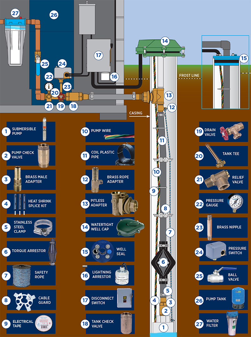
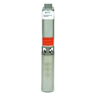
Pumps water from the well to supply pressurized water for the home.
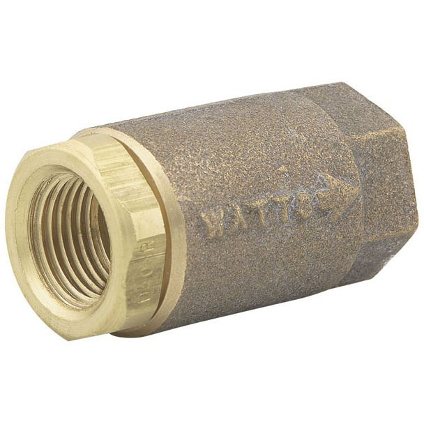
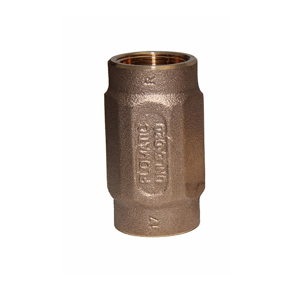
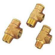
Located at the top of the pump, it prevents backflow into the pump and holds the head of water in the system.
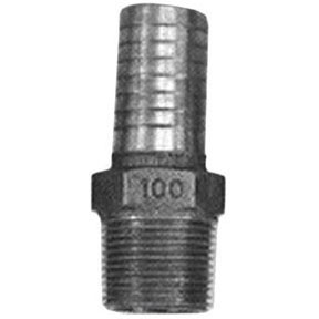
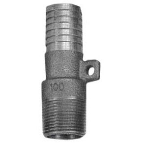
Provides connection between poly pipe and pipe thread.
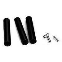
For waterproof electric cable splices in submersible pump installations.
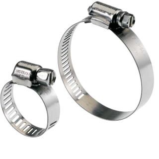
All-stainless steel clamps for dependable connections between pipe and insert fittings or torque arrestor.
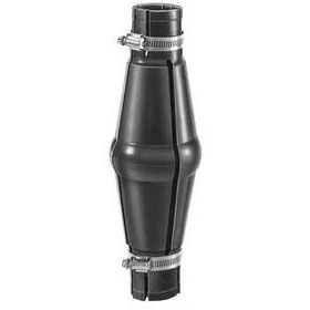
Installed directly above submersible pumps to protect pump and well components from starting torque damage.
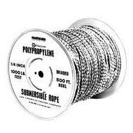
A safety line from the top of the well to the pump.

Protects submersible cable wires from abrading against sides of well.
Fastens Cable to Drop Pipe.
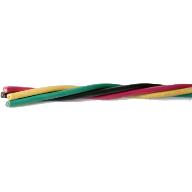
Wire that connects a submersible pump controller to the pump motor.
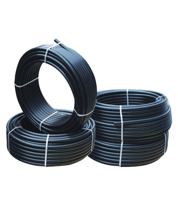
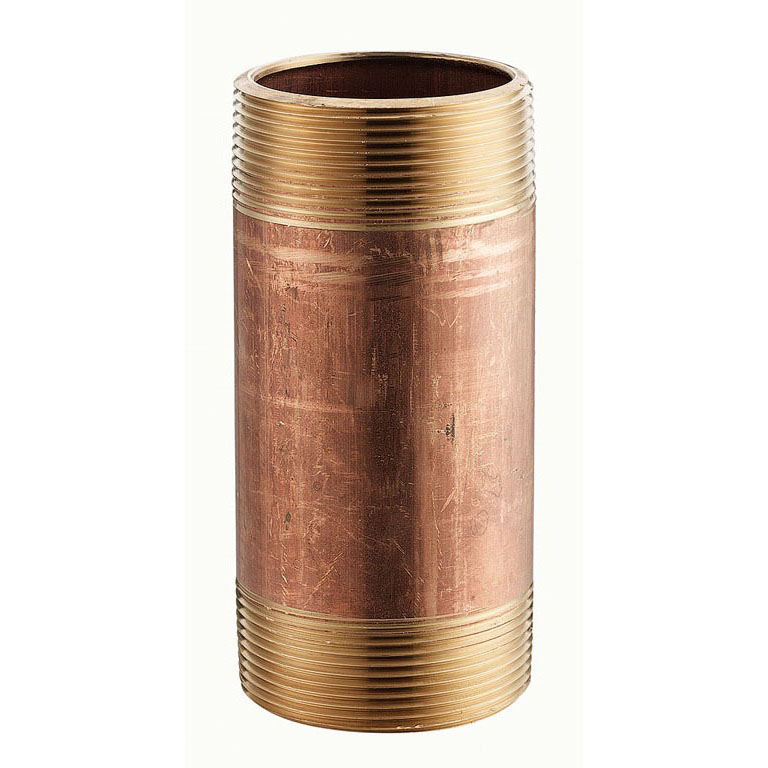
Connects the pump to the pitless adapter.
Connects the pitless adapter and the submersible pump with safety rope.
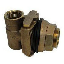
Provides a watertight, sanitary, removable connection between the pump and the house. Installed in casing below the frost line to prevent freezing.
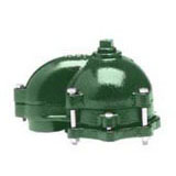
Inner gasket compresses to outside diameter of casing to provide a watertight seal. Top of cap removes easily to access well for service.
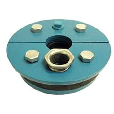
Used in above-ground installations to provide a positive seal inside casing.
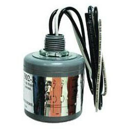
Protects pump motor and controls from voltage surges caused by lightning, switching loads, and power line interference.
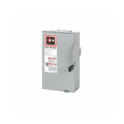
For electric control and distribution to the pump.
On pump installations, a tank check valve installed near the tank inlet holds water in the tank when the pump is idle.
For easy draining of the system.
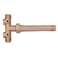
Connects water line from pump to pressure tank and service line from tank to house. Taps are provided to accept pressure switch, pressure gauge, drain valve, relief valve, snifter valve, etc.
Protects against pressure build-up. Should be used on any system where the pump could develop greater pressure than the maximum rating of the system. Part
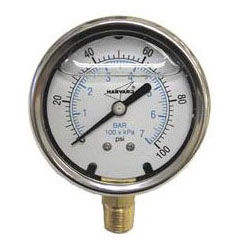
Measures water pressure in pressure tank.
Male threads allow attachment of pressure switch to tank tee.
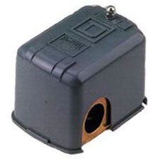
Signals the pump to start when the water system drops to a preset low pressure, and to stop when the high pressure mark is reached.
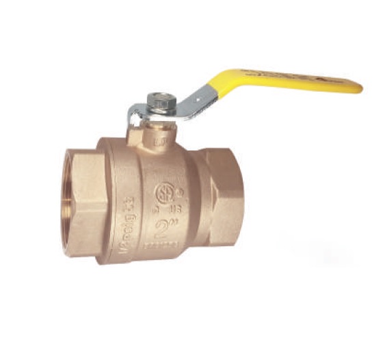
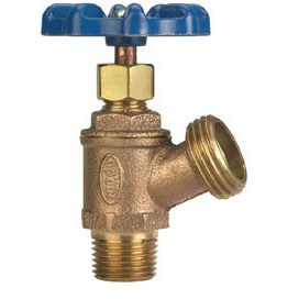
Acts as a shutoff valve on the supply line from the tank to the house.
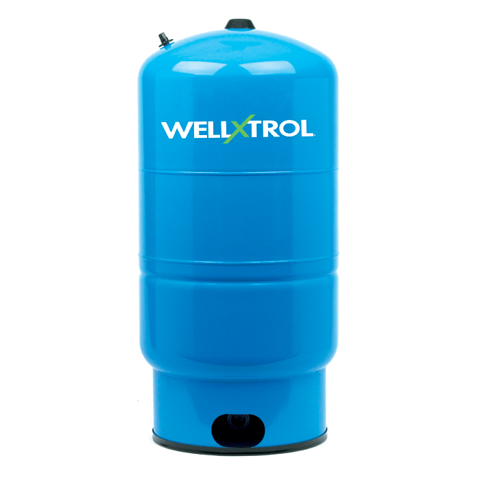
Container for storing water used throughout the home.
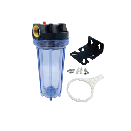
A point-of-entry, whole-house-filter that removes rust particles, sand, etc. from supply water.